
Project: Strengthening and rehabilitation of the steel structure of a Panda building
Location: Al Majardah, Saudi Arabia
Scope of Work: 3D laser scanning, structural assessment and design, fabrication drawings, fabrication, supply and installation of internal steel strengthening members.
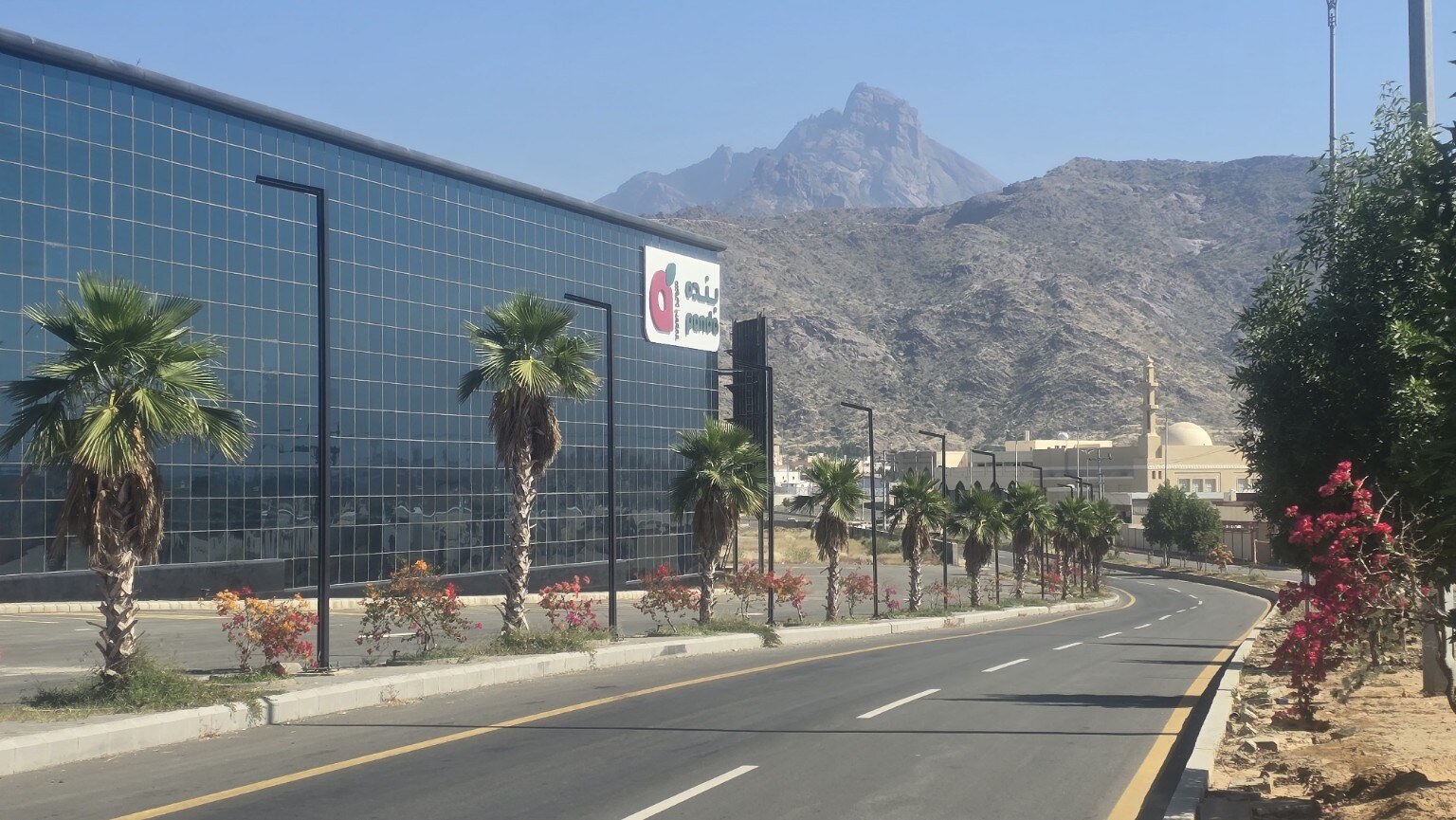
Condition before intervention
The building's roof suffered a partial collapse under wind loading, compounded by weakness in the existing steel structure. Although a previous contractor repaired and initially strengthened the roof, subsequent assessment found that the system remained weak and did not provide the required level of safety during future storms.
This was not an isolated damaged section that could simply be replaced. The issue involved the effective spans and existing deformation of the beams. The solution had to reorganize load transfer and increase roof stiffness without removing the roof covering or disrupting store operations.
Strict installation constraints inside an operating building
All work had to be carried out from inside the building while leaving the roof, shelving and goods in place. External cranes were unavailable, and the schedule was shorter than one month. Repeated manual measurement or cutting and reworking members on site was therefore impractical.
The method relied on prefabrication: accurately survey the existing geometry, then prepare each member and its connections in the workshop for installation in a planned sequence.
3D laser scanning: measuring the as-built structure
The work began with a three-dimensional laser scan from inside the building. The survey captured beams, columns and existing deformations at roughly millimetre-level accuracy. This was crucial because substantial deformation meant the roof no longer matched its theoretical geometry.
Small differences in levels or angles from manual measurements can leave a fabricated member unable to fit at roof level. The laser-scan model allowed the proposed strengthening members to be placed digitally and their lengths, angles and connection positions determined before fabrication.
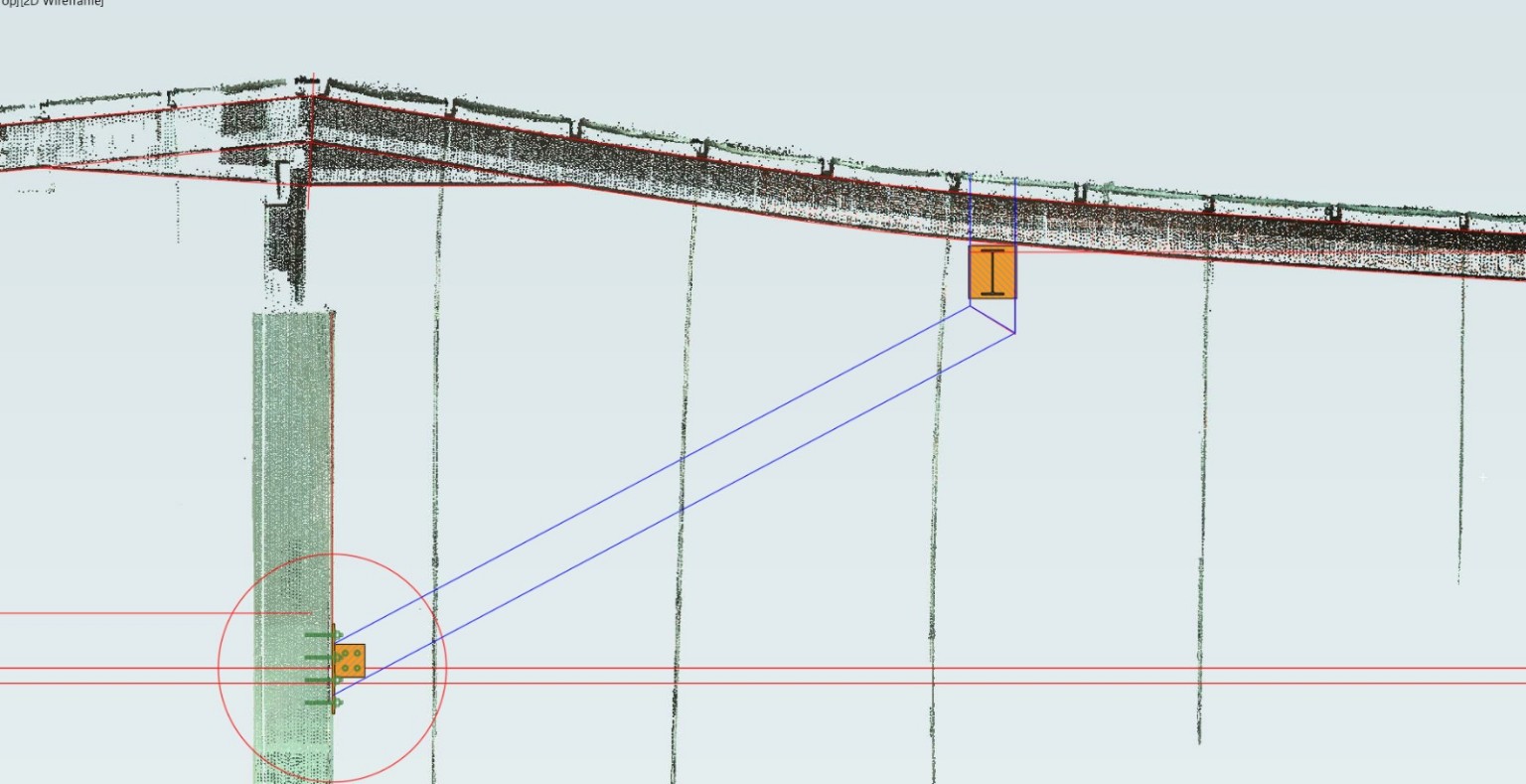
Once the actual dimensions were approved, detailed fabrication drawings were prepared for the members and connections. The steel pieces were then fabricated in the workshop and delivered ready for installation, limiting delays and improvised modifications inside the building.
Structural principle: reducing the effective beam span
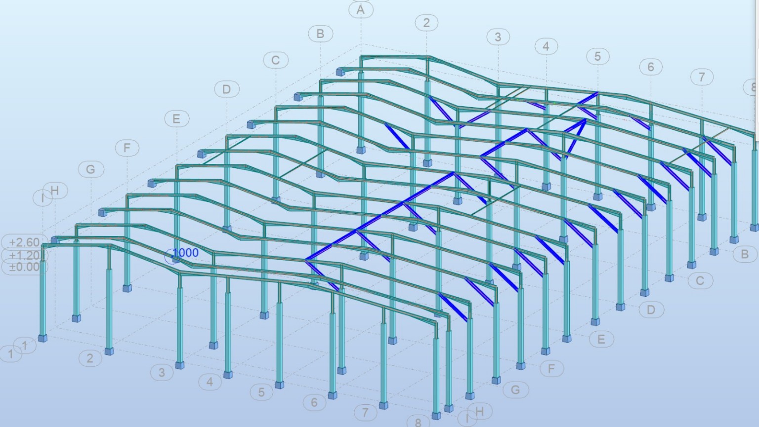
The added steel struts may look like extra dead load on the roof, but their structural function is to shorten the effective span of the weak beams, reducing bending moments, strains and deflections under load.
The struts extended from the columns to roughly one-third or one-quarter of each steel beam's span. Acting primarily in compression, they intercept part of the roof load and transfer it to columns with suitable stiffness and capacity, instead of leaving the entire load on the long beam span.
Pinned connections to control the load path
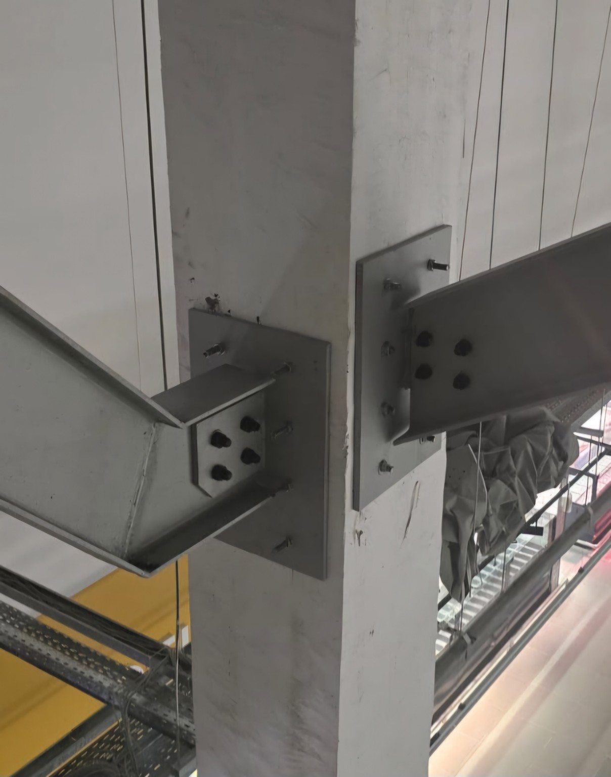
The strut connections to the columns were designed as nominally pinned, non-moment-resisting connections. Their purpose is to transfer the required compression force into the columns while limiting bending-moment transfer. This detailing keeps the system aligned with the design load path and avoids imposing unaccounted moments on the columns.
Moving and installing members weighing up to 200 kg
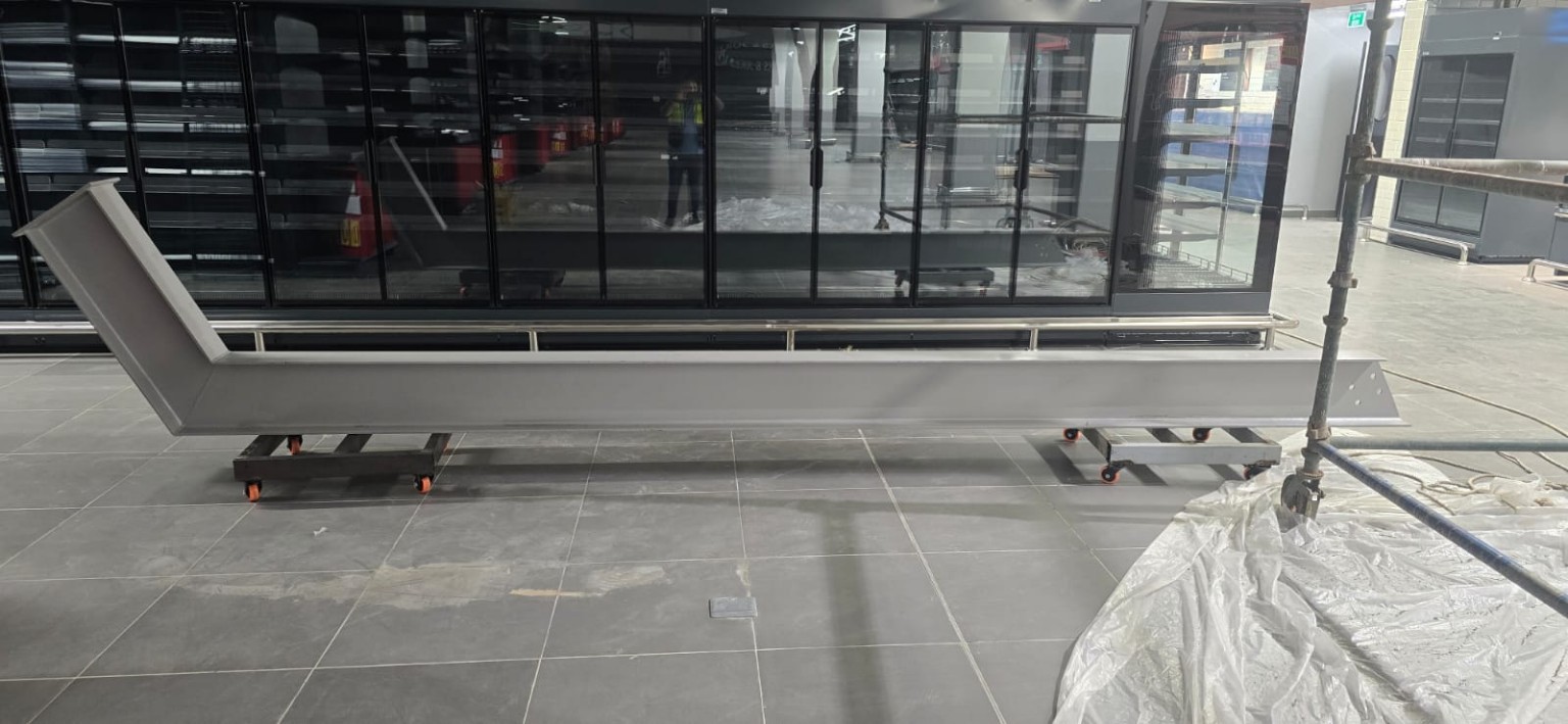
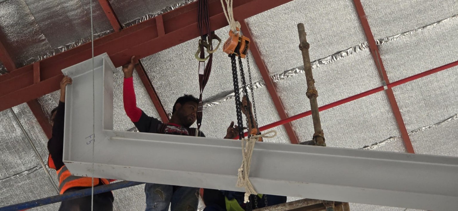
Some strengthening members weighed about 200 kg. An external crane could not be brought in, so an internal lifting arrangement was prepared for the heavy pieces, with transport trolleys used to move them through the building without damaging the aisles or store contents.
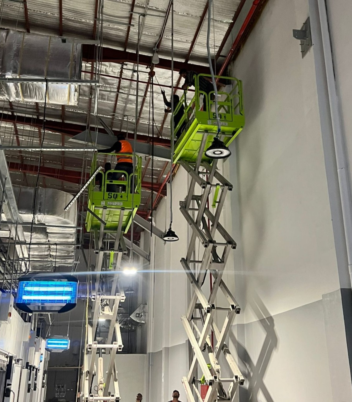
Mobile elevating work platforms provided access to roof level for fastening and welding. The steel pieces were lifted and guided gradually into their final positions. This approach kept the work inside the building while preserving the roof, shelves and stock.
Outcome
After strengthening, the structural system became more stable under operational and wind loads. This was achieved by reducing the beams' effective spans, directing forces into the columns and installing prefabricated elements matched to the structure's actual deformations and dimensions.
What made the difference? The combination of three-dimensional laser scanning, specialized structural design, prefabrication and a carefully planned internal installation sequence made it possible to complete the strengthening within the required time without removing the roof or interrupting the facility.