
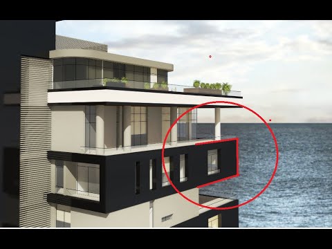
This article examines the structural design of a long reinforced concrete cantilever in Lamina Tower, where the length of the projection and architectural requirements called for more than a conventional beam solution. The study used three-dimensional analysis of the concrete members before selecting a reinforced concrete Vierendeel girder to create a clear, safe load path from the free end to the load-bearing elements within the tower.
What is a long concrete cantilever?
A cantilever is an element that extends beyond its support without direct support at its free end. It may form part of a facade, roof, balcony or projecting building volume. Short cantilevers often have relatively straightforward behavior. As the projection length grows, bending moments, shear forces and deflections increase substantially; controlling deformation and detailing the fixed-end region become critical.
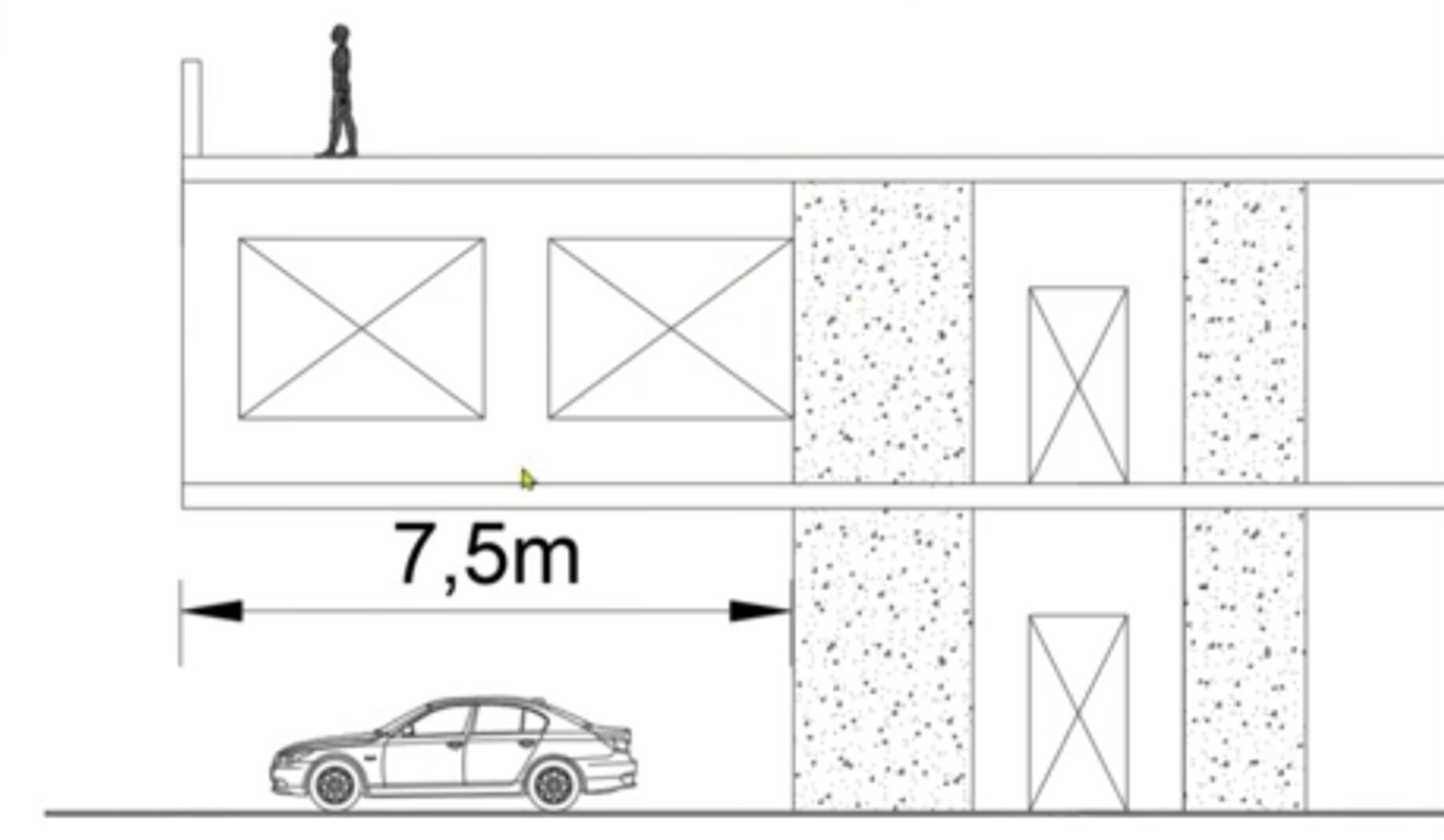
Section capacity alone is therefore insufficient: the engineer must examine the load path, support stiffness and interaction with connected slabs, beams and vertical elements.
The challenge in Lamina Tower
The main challenge was to achieve the required architectural projection without adding columns or exposed members at the free edge. All loads must return into the building through a carefully designed structural system while bending, shear and deflection remain within acceptable limits.
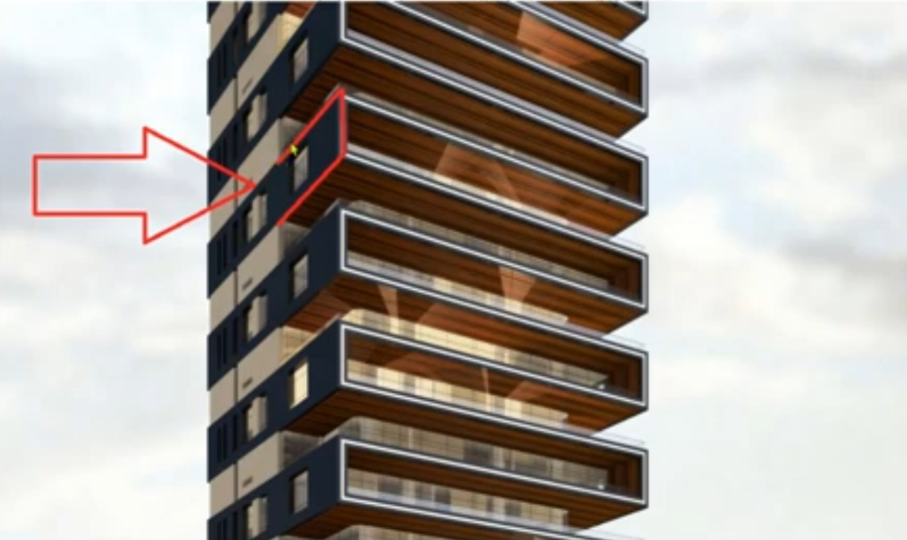
A long cantilever also responds to more than vertical gravity loads. Variable loads, wind effects and long-term concrete deformation must be considered as part of one system. The first step was therefore to build a three-dimensional model that represents the actual conditions more accurately.
Why did we use three-dimensional analysis?
In routine cases, line elements for beams or surface elements for slabs may suffice. Where load introduction and support regions are deep or geometrically complex, three-dimensional solid elements help reveal how stresses develop within the concrete volume rather than only along an assumed beam axis.
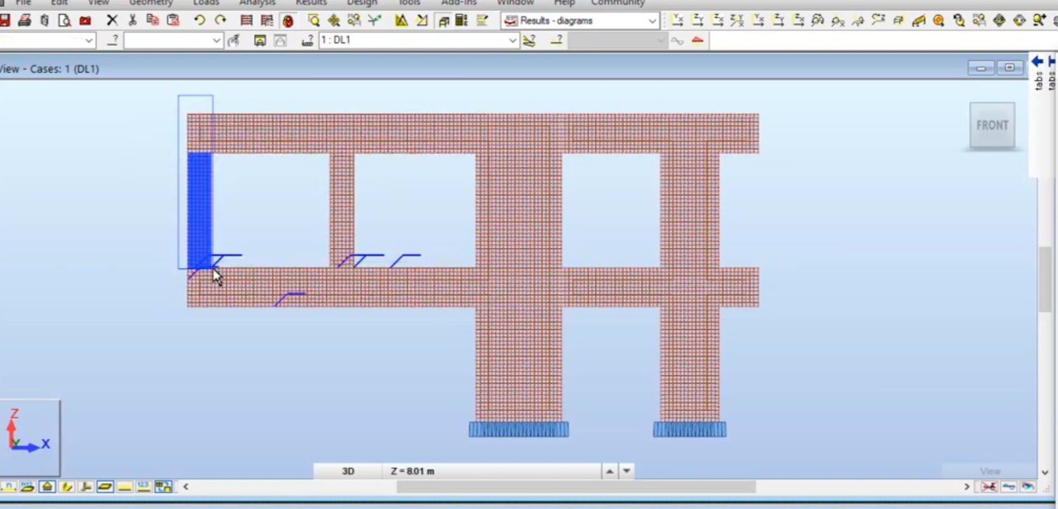
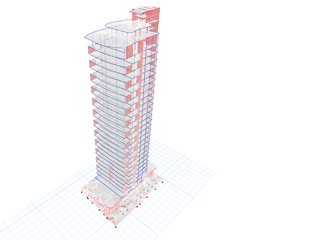
This analysis makes it possible to study stress distribution, concentrations, deformation directions and the transfer of loads from the cantilever into the supporting region. The structural solution can then be refined based on expected behavior rather than a simplified model that overlooks the geometry.
Vierendeel girder: the structural concept
A Vierendeel girder is a deep frame with top and bottom chords and vertical members, but without the inclined diagonals of a conventional truss. It can therefore leave clear openings within its depth when architectural or operational requirements prevent diagonal bracing.
Here the concrete girder transfers forces through its members and joints. Instead of concentrating the demand in one long member, forces are redistributed between the top and bottom chords and the verticals, then delivered to the support region and principal tower members. This is not a simpler system: its behavior depends directly on joint stiffness, concrete continuity and accurate reinforcement detailing.
How do loads travel through the system?
Loads begin at the projecting cantilever and free edge, then pass into the concrete elements of the Vierendeel girder. The chords and verticals work together to resist bending and shear before delivering those forces to the support region inside the tower. Every link in that chain matters: the cantilever, girder, joints and the vertical elements or core receiving the forces.
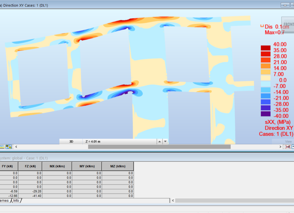
Any break in this path, or insufficient stiffness in one element, can cause greater-than-expected deformations or change how forces are distributed. That is why analysis must be connected to construction detailing: the design succeeds only if the intended load path is actually built.
Essential structural checks
After building the model and selecting the structural system, the analysis results are reviewed under the applicable load combinations. The checks include bending and shear, serviceability deflections, stress concentrations and the receiving structure's capacity to carry the forces from the cantilever.
- Bending moments and shear forces in the cantilever and Vierendeel girder.
- Stresses and deformations in critical regions, especially near the support.
- Serviceability deflections, which affect the architectural appearance and operational comfort even when strength requirements are met.
- Capacity of the tower's supporting elements to receive the forces transferred from the cantilever.
- Reinforcement, joint and continuity details that allow the frame to act as one unit.
Construction detailing is essential
For long cantilevers and concrete Vierendeel girders, the task does not end with model results. The structural concept must be translated into buildable details: reinforcement placement, development lengths, splice locations, dense reinforcement around joints and the casting sequence where required. These details ensure that the structure behaves as assumed in the analysis.
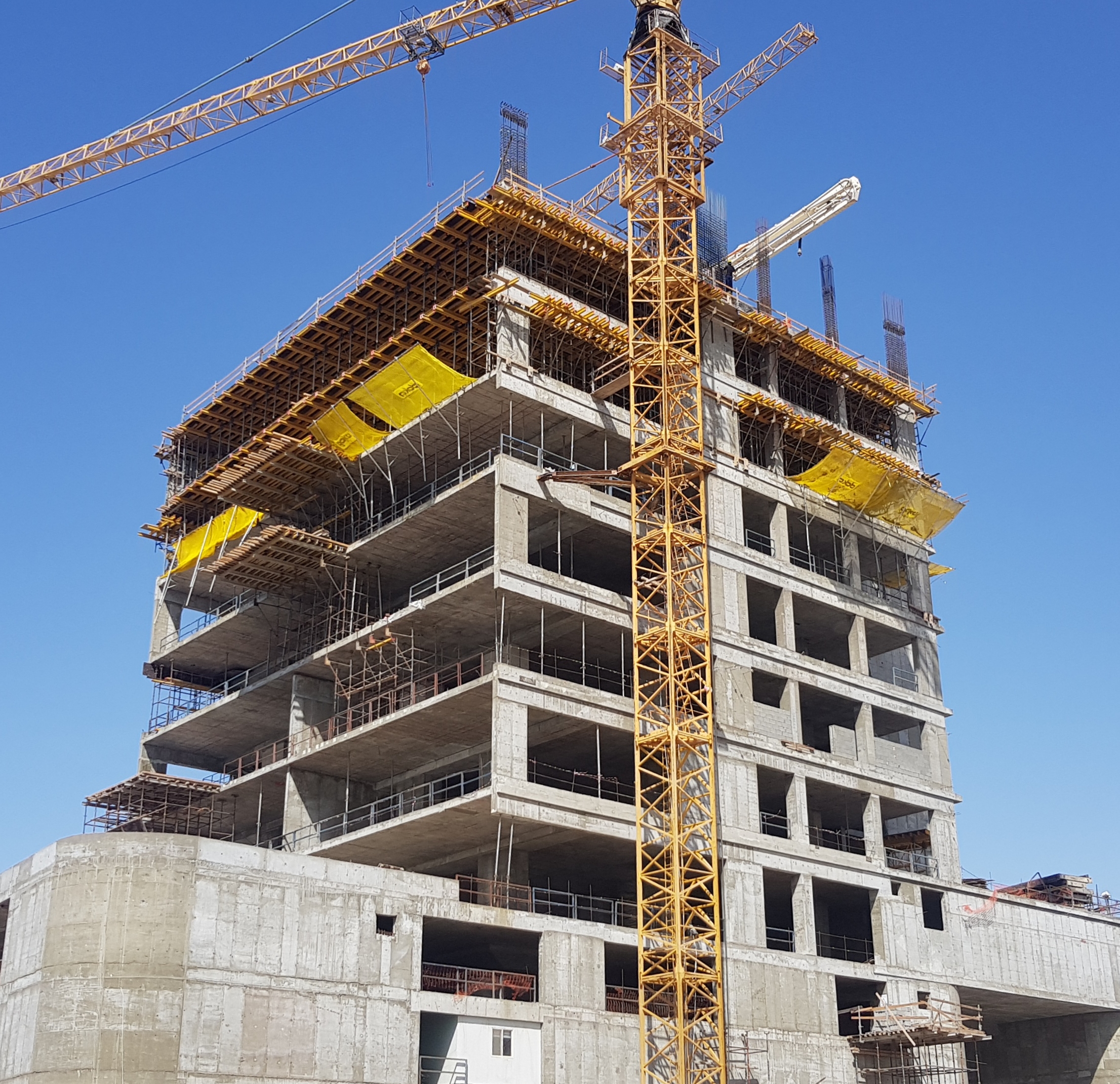
Early coordination between structural and architectural engineers is also needed to fix openings, services and clearances. Late changes within the girder depth or at the support can directly affect the efficiency of the solution.
What can engineers learn from this case?
A long cantilever cannot be solved simply by increasing slab thickness or adding reinforcement. The right starting point is to understand the load path, select a system that fits the architecture and analyze it with appropriate detail. A Vierendeel girder can be effective when both structural depth and clear openings are needed, provided its behavior is fully understood and detailed.
Conclusion
Three-dimensional analysis provided a clearer picture of the long concrete cantilever in Lamina Tower and supported the choice of a concrete Vierendeel girder to transfer loads and control deformation within the architectural constraints. An appropriate analytical model, a clear load path and precise construction details together turn the architectural challenge into a safe, buildable structural solution.